
© 1998-


Rebuilding the
Heater Box
Heater Core Considerations
Part 2
If you are going to the extent of rebuilding/resealing a heater box, I strongly recommend
installing a NEW heater core. While radiator shops can boil out your old core, they
can not completely clean it inside removing all corrosion, rust, and calcium deposits
as they can by "rodding" out a radiator. If you have an old core boiled out, some
of the corrosion inside will be removed, but not all. You will end up with a core
that has less performance than new from the start, and, as a result, you will have
less performance from you heater. If you live in southern California or Florida this
would probably not be a big problem. If you live in the middle parts of the country
it can be a problem. If you live in the north it will be a problem. New cores are
available for around $45 from all the Falcon vendors. As mentioned above, I have
never been cold in my Falcon when I have had a new core in my heater-
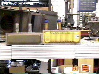
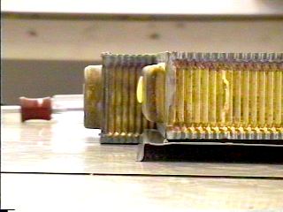
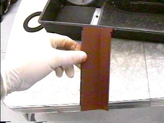
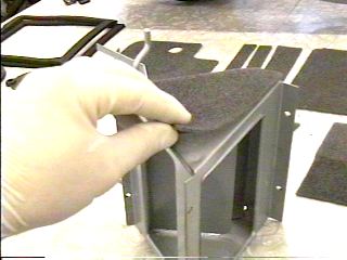
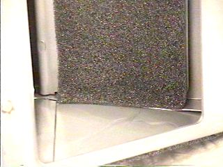
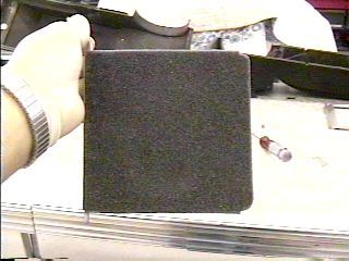
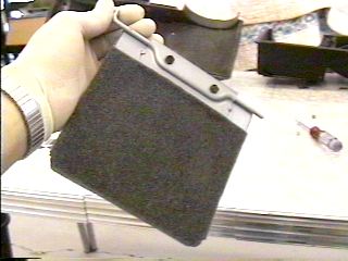
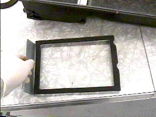
The photo on the left shows the thickness of the two heater cores available for our Falcon heaters. The core on the left is used with a spacer in the front half of the box. The one on the right is used without a spacer. My '64 Sprint heater box did not have a spacer, and the thicker core was needed. My '65 Futura heater box did have the spacer so the thinner core was needed for it. If you have a spacer in your heater, be sure to keep it since the thinner cores are easier to find. The photo on the right shows how the spacer increases the height of the thinner core to match the thicker core.
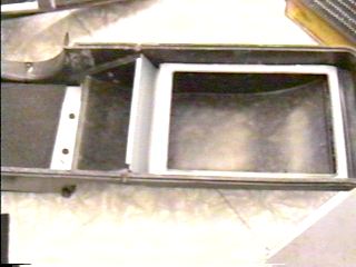
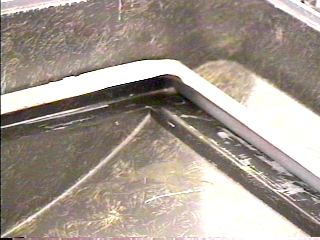
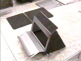
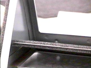
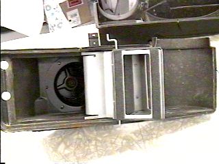
The left photo shows the airflow director/spacer piece in the front half of the box.
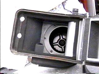
The right photo is a close-
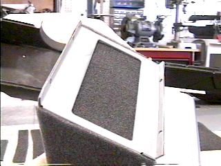
This photo shows the single metal airflow director that is used in place of the airflow director/spacer mentioned above on earlier models. If you only have this piece in your heater, you should use the thicker heater core. If you are unable to locate a thicker core, you can use the thinner one by keeping the old core seal pieces and putting the new ones on top of them to take up the space. The proper height core is the best option however.
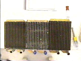
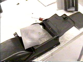
Another consideration with the core is length. The core on the left is the thinner core and 1/2" shorter than original equipment. The center core is the thicker core but also 1/2" shorter than original equipment. The core on the right is original equipment from my '64 heater box. It is the thicker core and the correct length. Unfortunately, I have not been able to find an exact replacement core lengthwise. However, as outlined later in this edition, the shorter length of the core is easily compensated for.
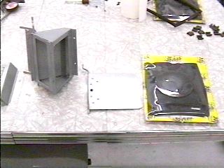
The heater seal kit comes in a shrink wrapped package as seen in the right side of the above photo.
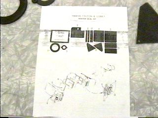
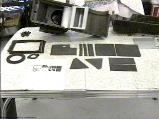
The instructions (left photo) are not as helpful as they could be. It helps if you lay out the foam pieces as they appear in the instruction sheet as seen in the right photo. The foam pieces are numbered on the instruction sheet and referenced by a corresponding number in the exploded drawing.
The drawing is less than accurate in its depiction of the temperature regulator assembly, and it can be confusing as to which side(s) what seals go on just from looking at the drawing. The photo on the right shows the regulator in the proper attitude as they are attempting to show in the drawing.
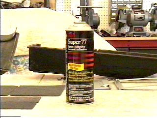
A spray adhesive is ideal for applying the foam seals to all parts of the heater.
I have found "3M Super 77" to be superior. It is like a spray contact cement. You
can apply the adhesive to one surface or both. For applying the foam seals to the
various metal surfaces in the heater, I recommend only applying the adhesive to one
surface. That way if you make a mistake in alignment, the foam piece can-
Be sure to "dry" fit all foam pieces before applying adhesive to make sure you not only have the right foam piece mated to the correct place, but also that you apply adhesive to the correct side of the foam piece. I strongly recommend applying adhesive to one piece of foam at a time. Trial fit the piece, then apply adhesive to the correct side, then apply the foam piece to the metal part. Use light pressure when applying the foam piece as hard pressure will result in depressions where your fingers pushed the foam down which can result in a less than perfect seal.
While applying this foam piece to the valve door in the temp mix valve assembly, it got slightly stretched as it was applied from top to bottom. I checked that it still had a good seal, and then trimmed the excess at the bottom with a razor blade.
The four photos above show various views and stages of applying the foam seals to the temperature regulator assembly.
This is the heater on/off door that fits in the front half of the box. Make sure
the large foam piece goes on the side without the rod mounting bracket (left photo)
and the smaller one on the other side (right photo). Note that these pictures show
the control rod already installed in the door-
After the vent door on the front box half has been cleaned up, all rust removed, and primed/painted, the foam seal can be installed on it. Take care to apply adhesive to the correct side of the seal, and try to get the edges of the seal inside the lip of the outer edge of the door.
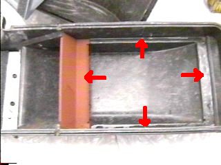
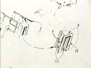
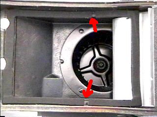
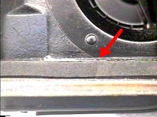
There are two heater core seals. One goes in the rear heater box half and will be covered later. The other goes either on the core spacer as shown in the left photo above, or, if there is no core spacer in your heater, it goes in the front half of the heater box as shown by the arrows in the right photo above. There is nothing to hold the small air deflector (orange item in right photo) in while you put the two halves back together again except the left edge of the core seal, so be sure to use plenty of adhesive on this seal. Once the halves are together the air deflector will be held in place by other items, so the extra adhesive is just to help hold it in place during assembly.
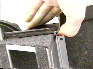
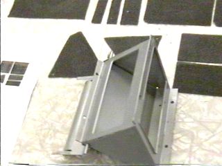
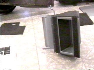
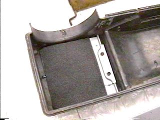
Before you can apply the other core seal, you need to install the temperature regulator assembly in the rear box half. You will need to lift the edge of the box some as shown in the left photo in order to slide the assembly completely in place without running the risk of damaging the foam seal on the top and bottom of the assembly. The right photo shows the temp valve assembly installed and screwed in place.
Since the new heater core for this box is one half inch shorter than original equipment, the seal on this side of the core must be shortened by a half inch. I applied a light coat of adhesive to the seal then put it in place as seen in the left photo. Then I cut 1/2" out of the top and the bottom as indicated by the arrows in the right photo.
I then carefully peeled off the right side of the seal and moved it over so the ends
mated tightly with the other side of the seal as seen in the left photo. The right
is a close-
Install the heater on/off control rod back in the front half of the box (if you removed it), then install the door on the control rod. There is usually enough give between the rod and door bracket to allow for up/down adjustment to keep the door from scraping top or bottom when the door is in movement.
Installing the Foam Seals
This is the end of the Heater Rebuilding Edition
Part 2

Feel free to save this page to your computer for your personal use and future reference-
If you have comments or suggestions, email me at joe@joesfalcon.com