
© 1998-


Rebuilding the
Heater Box
Reassembling Heater Box
Part 3
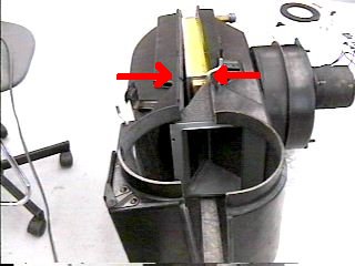
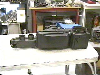
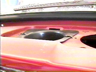
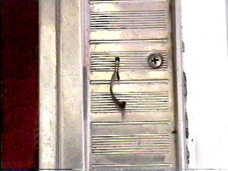
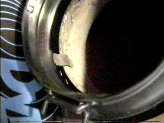
Install the heater core in the rear half of the box with the tubes sticking out the
back. Then join the halves back together again. Be sure to help lift the top of the
front half as it slides over the foam seals on the temp valve assembly. Although
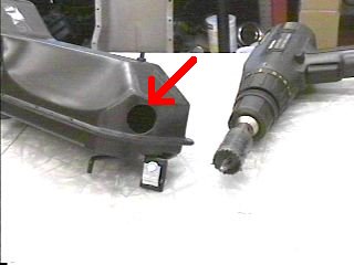
difficult to see in the photo, there is an indentation in both the front and rear
halves for the temp mix valve control rod to ride in (arrows in left photo). The
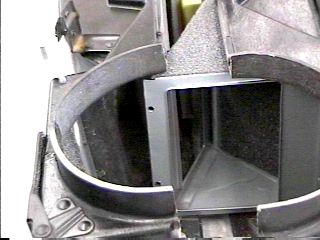
right photo shows a close-
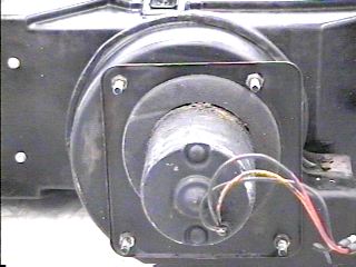
The left photo shows the firewall seal (with adhesive sprayed on) which seals the hole for the fan as it protrudes into the engine compartment. The right photo shows the seal installed. I kept the old seal in place also just for some added thickness to the seal.
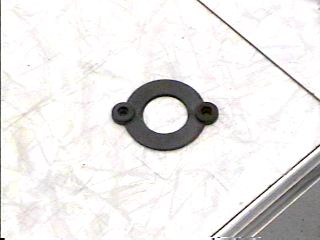
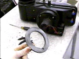
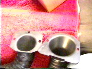
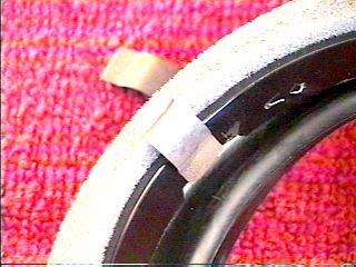
This is the seal that goes between the fan motor and the fan housing. If you remove the fan and motor from the fan housing, it will be easy to see where this seal goes. I replaced the seal on my '64 heater box, but chose to not separate the motor from the housing on this box.
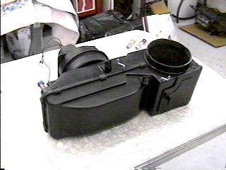
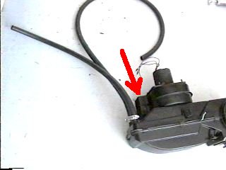
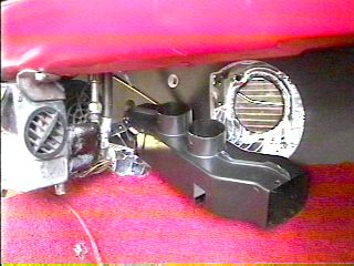
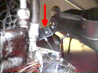
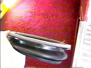
The left photo shows the box assembled. The right photo shows new heater hoses installed. The defrost/floor mix valve attaches to the fan housing as shown by the arrow in the right photo. I did not install the defrost/floor mix valve in the heater box for this car because the under dash air conditioning unit would not allow the additional length of the box to make the turn with the item installed. I needed to attach the defrost/floor mix valve after both were under the dash.
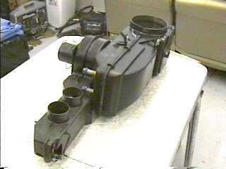
This is what the assembly looks like with the defrost/floor air valve attached to the heater box. It attaches with four small sheet metal screws that go into the outlet of the fan housing. If you do not have an under dash air conditioning unit, installing the defrost valve on the box now will make installation in the car easier.
The box is now ready to install in the car.
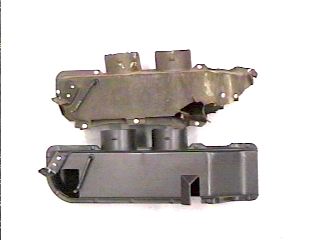
The old defrost/floor mix plenum, which was originally made of cardboard, is on top
in the left photo-
The original defrost outlets were also made of cardboard. The left photo shows two available replacement outlets. The one on the left was in my '65 when I bought the car. You'll notice it is much smaller than the new one on the right. It is small enough that it fit loosely in the dash and rattled as I drove the car. The one on the right (left photo) I had on hand for my '64 Sprint restoration, so I tried it and it fit perfectly (I ordered another set for the Sprint). Not only do these fit better, but the hole is larger and allows for better airflow. Note, however, that it is designed to fit facing to the front rather than to the side as it seems it should, as seen in the right photo. These larger ones I got from Melvin's Classic Ford Parts.
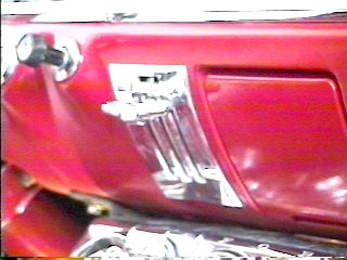
As mentioned above, the stock factory air conditioning unit was in the way and prevented
the defrost/floor mix valve from being attached to the box prior to installing it
in the car. The left photo shows the valve in place with the control cable installed.
The right photo is a close-
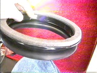
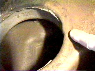
The flexible air plenum duct is shown in the left photo. The side with the foam seal goes up against the bottom of the cowl, and the other side goes over the hole in the top of the heater box. This plenum is held in place against the cowl with clips, shown in the right photo. The clips attach to the plenum where my finger is in the left photo. The plenum is then pushed up to the cowl with the clips inside the hole as outlined below. It must be noted that in the absence of these clips, some have drilled holes in the cowl and screwed the plenum to the cowl. The only real problem with this is that the cowl is both an air duct and a water duct. As rain water or road water that is splashed up enters the cowl area (the slotted holes between the hood and the windshield) it runs to the sides and exits just behind the rear part of the front fenders. If holes are drilled into the bottom of this water duct, they will eventually rust out and water will then drip or run into the interior of the car from under the dash. It is possible to protect the drilled holes, but it is probably far more work than just locating the clips from a junk yard or Falcon parts vendor.
The left photo shows a clip installed in the plenum piece where the indentation is. The other clip is installed on the opposite side as shown in the right photo.
The left photo is looking up at the bottom of the cowl under the dash where the plenum attaches. The clips attach at the protrusions where my finger is pointing. The right photo shows the plenum installed. Note the clip holding the plenum to the cowl.
Installing the Heater Box and Making Adjustments
Everything is now ready for the heater box to be installed in the car. From under
the dash, slide the heater hoses into the holes in the firewall as you lift the heater
box up into place. If you did not install the defrost/floor mix plenum onto the heater
box previously, do it now. Take care as you slide the fan motor through the hole
in the firewall that the wires to the motor are not pinched in the process. Maneuver
the heater box until the four bolts surrounding the fan motor slide into their respective
holes. Install the nuts on these bolts in the engine compartment and reattach the
fan motor wires and ground wire. Attach the heater hoses to the intake manifold,
and water pump and refill the cooling system with fresh clean anti-
The three control cables need to be attached and adjusted as the heater box is installed.
This is a relatively easy procedure. First, move all the control levers to just short
of the full up position (as seen in the photo above). Then put the particular valve
you are adjusting in the corresponding position. Place the cable wire loop over the
control rod and pull the cable slightly to make sure the valve is fully seated (make
sure the control levers don't move), then tighten the cable clamp. Check the operation
of all three valves for ease of movement and complete seal when closed. Re-
The Defrost/Defog System
Installing the Flexible Air Plenum Duct
This is the end of the Heater Rebuilding Edition

Feel free to save this page to your computer for your personal use and future reference-
If you have comments or suggestions, email me at joe@joesfalcon.com