© 1998-


Doors &
Windows
Part 1
Removing the roll up window and associated mechanisms from the door.
Without question, removing the windows from the car was the most challenging mini-
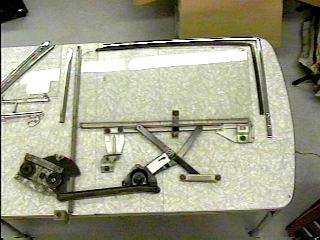
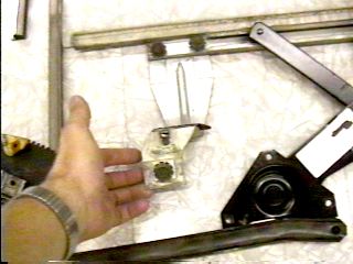
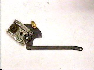
Illustration on left is from the ‘64 Falcon Shop Manual and used pursuant to permission granted by Ford Motor Company. The photo on the right shows the actual parts after being removed from the car.
The shop manual illustration shows the roll up/down window and the vent window and its frame. Starting with the main window, there is a front glass run and a rear glass run. The front run is pushed into the vent window frame and appears to be a part of the frame, but it is just held in a channel in the vent window frame by pressure (it can be pried out). It starts at the top of the rolled up window and extends down into the door cavity attaching to an adjusting bracket near the bottom of the door. The only adjustment to this run is at the bottom and moves the top of the vent window frame and the roll up window toward the middle of the car or away from the car so as to obtain the correct fit with the windshield weather strip. The rear run starts at the rear top of the door and extends into the door cavity. It has two adjustments. The one at the bottom moves the top rear of the roll up window in and out to obtain proper fit with the weather stripping in the roof and with the rear window. The top adjustment moves the run closer to the window frame for a close fit to remove rattle. There are two up stop adjustments (front & rear) and one down stop adjustment.
The scissors assembly (called the arm & plate assembly in the illustration above)
looks like an "X" in the middle of the illustration and in the bottom center of the
right photo. The top two arms attach via rollers into a channel in the bottom of
the window frame. The lower right arm attaches via a roller into a channel (called
a "Bracket Assembly" in the illustration) bolted to the door frame-
The vent window frame is held in by the front roll up window run, a bolt at the rear of the frame just below the top of the door (the hole in the door is hidden by a Sprint or Futura emblem), a bolt on the front of the frame (which is normally covered by weather stripping) and by an adjustment bolt at the front bottom of the frame which also adjusts the top of the vent window frame.
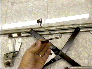
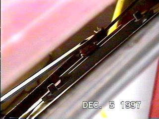
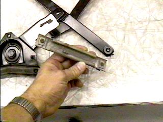
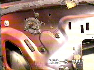
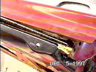
The left picture is the fixed bracket for the front up stop of the roll up window (pictured here with the window rolled down). It contacts a bracket higher up in the door cavity which I am holding in the upper right photo. This bracket bolts to the frame of the door and adjusts via a slotted bolt hole to obtain the proper up stop for good fit with the roof.
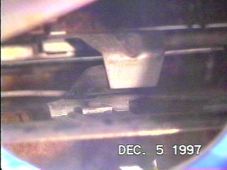
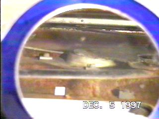
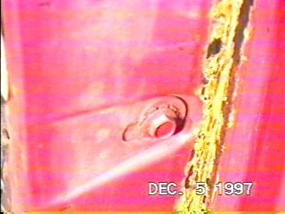
This picture is looking up into the door cavity through a mirror at the two stops making contact, after the window has been rolled up.
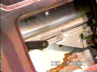
This is the rear up stop bracket on the right of the photo, and the rear scissors arm (black) on the bottom of the window frame.
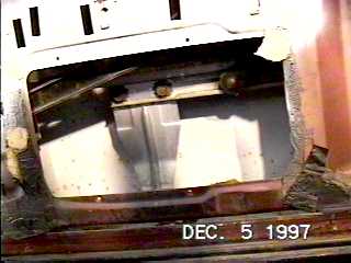
Although difficult to see in the left photo, slightly right of center is the down stop. It is held on by two bolts visible on the right side of the left photo (one just above the date and the other about midway up in the photo). Note that these bolt holes are slotted for up and down adjustment. The right photo shows the down stop bracket after removal from the car.
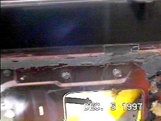
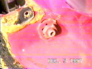
This is where the scissors assembly mounts to the door. The photo on the left is
looking inside the door cavity through a mirror, the right photo shows the location
of the three bolts holding it in place on the passenger compartment side of the door.
Note also in the lower portion of the right photo the arm rest blind nuts in the
slotted holes-
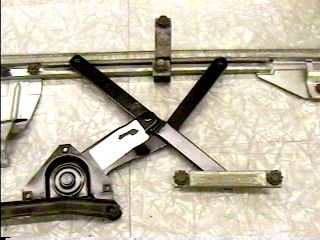
This is the scissors assembly after removal from the car (actually, this is a new assembly, the one removed was pretty worn). In the lower right of the photo is the channel for the lower right arm of the scissors and is discussed more below.
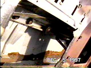
This is the channel (called a Bracket Assembly in the shop manual illustration above) for the lower right arm of the scissors that bolts to the door. The left photo is looking inside the door cavity from above. The right photo is after removal from the car.
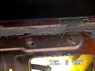
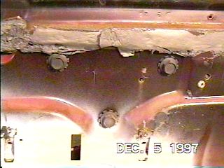
These pictures show the bolt locations for the Bracket Assembly channel mentioned in the previous paragraph above. Note in the right photo, after the bolts are removed, that the bolt holes are slotted in a 45 degree angle so that the channel adjusts either forward and up, or rearward and down. Note also the gray "goo", or strip caulk, that held the clear plastic sheet in place behind the door panel and sealed the door cavity from the passenger compartment.
This picture shows the 4 bolts holding on the window regulator. The lighter bolt in the top left is the lower front adjustment bolt for the vent window frame.
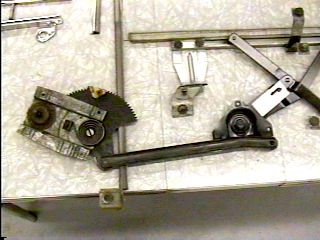
The left picture shows the regulator after removal from the car. The right photo shows the regulator as it would attach to the scissors assembly.
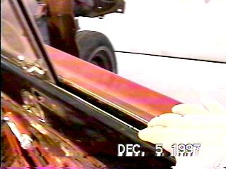
After the regulator, the scissors assembly, and both up stops are removed, the window felts must be removed before the window can come out. These felts are held into the door by clips and can be pried out with a small screwdriver (note that the felts for the rear windows are stapled into place and are more difficult to remove). After the felts are removed, the window can be removed by lifting it up to near the top of its travel, then tilting the top of the window toward the back of the car, and pulling it out of the door cavity. Then remove the down stop bracket.
The rear glass run is held in by an upper in/out adjusting bolt (left photo) and a lower left/right adjusting bolt (right photo). The screw hole above the adjusting bolt in the left photo is for a weather stripping piece. The yellow in the photos is old 3M Weatherstrip Adhesive.
This is the end of the Doors & Windows Edition
Part 1

Feel free to save this page to your computer for your personal use and future reference-
If you have comments or suggestions, email me at joe@joesfalcon.com