


Shoulder harnesses (whether they be two separate belts--seat belt and shoulder belt,
or a more modern 3 point shoulder/lap system) are a great safety feature in any vehicle.
Unfortunately, adding them to an older car can be a challenge, especially to a convertible
or hardtop. In an actual high speed crash situation, seat belts and shoulder harnesses
absorb tremendous amounts of energy which converts to physical stress on the attach
points. It must be stated that without an engineering background, it is impossible
to ensure with absolute certainty that attaching shoulder harnesses or seat belts
to any part of the car is a fully safe proposal, However, common sense dictates that
some locations would easily withstand the stress, while others would not, and some
others would be questionable. If a spot will obviously not stand the stress, don't
use it. If it is questionable, reinforce the area by welding in additional structure
to beef up the area so it is easily able to handle the stress. For example, attaching
a shoulder harness to any interior decorative trim piece would be not only unsafe,
but also absolutely useless. On the other hand, attaching to a solid heavy gauge
steel frame member would easily handle the stress--unfortunately, there are precious
few such areas where shoulder harnesses could be attached. So that leaves us with
areas of structure under decorative interior pieces to attach to. Again, without
an engineering degree, it is difficult to ascertain whether these structural areas
are sufficient. When in doubt, do more than might be needed. As a disclaimer, the
author takes no responsibility for the correctness or soundness of the material herein,
or the safety of installing a three point shoulder harness in the manner prescribed
in this web page. The information herein is simply to show how and where I chose
to install a 3 point shoulder/lap belt system in my '65 Falcon hardtop and is for
your consideration only. I chose an inertia reel kit offered by Melvin's Classic
Ford Parts. Other kits are available through several sources.
Owning both a convertible and a two door hard top, the difficult portion of the installation
was going to be the upper belt slip mounting bracket--also known as the third point
in a three point system--that goes just behind and above the shoulder. In a two door
sedan, this bracket can easily be added to the frame directly in front of the rear
window. On a four door it can easily be mounted in the pillar frame between the front
& rear doors. However, neither a convertible or a two door hardtop has these frame
pieces to attach to so other options needed to be considered. I had originally thought
I would mount the bracket in the roof by welding in a bunch of extra metal on each
side behind the headliner. But, I wasn't ready to repaint the car if the heat from
welding discolored or burned the exterior paint. In addition, there just isn't much
framework in the roof area to weld to with confidence in its structural integrity
without adding a great deal of metal the entire length of the roof line. Obviously,
in a convertible the roof location is not available. In looking at other options,
the only other place I could come up with was directly behind the door frame, right
below the front portion of the rear rollup window. The problem there was not interfering
with window movement or the decorative interior trim when additional structure was
added.
Front Seat Three Point Shoulder/Lap Belts
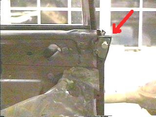
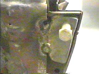
The left photo above is of the rear edge of the drivers side door jamb and area directly
under the rear roll up window--the decorative metal trim, vinyl covered side panel,
armrest and window crank have been removed. As seen in the left photo above, I chose
to anchor the belt in the forward upper corner of the rear seat panel area--the photo
shows the bracket already welded in place (red arrow). The right photo above shows
the bracket before installation. Iýÿmade the bracket from 1/4" by 1" bar stock I
got from a home improvement type store (Home Depot) for just a few bucks. I held
the bar stock in place and traced the approximate shape it needed to be to fit the
space and then did a combination of sawing, cutting (with a Dremel tool) and grinding
till the piece fit perfectly. I then cut/ground 3 more pieces to match the first.
I took two of the pieces and welded them together to make a 1/2" thick bracket, and
welded the other two together as well. (Although I've done some Oxy/Acetylene welding
previously, I'd never done any arc welding prior to this. However, with the help
of the video that came with the Lincoln Mig welder, and some practice on some scrap
pieces, these welds turned out quite nicely!) I then held the completed bracket in
place and "eyeballed" the position for the hole that the bolt will screw into. I
drilled the hole in the bracket on the drill press, and then held the bracket back
in place in the car and drilled a hole through the frame through the door jamb to
the outside portion of the door jamb so that the bolt would go through the bracket,
through the door jamb frame, and have a nut on the other side (as seen in the photo
below). I then tapped the hole in the bracket for a 7/16" x 20 threads per inch bolt.
I then temporarily bolted the bracket in place while Iýÿtack welded the bracket to
the frame, then removed the bolt and finished welding the bracket in place. Then
Iýÿtemporarily installed the decorative metal trim piece on the inside of the car
so I could, through the threaded hole, mark on the inside of the decorative trim
piece where the hole needed to be drilled for the slip bracket (third point) bolt.
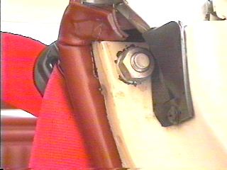
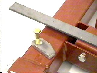
The left photo is a close-up of the bracket in place. The right photo is of the nut
on the other side of the door jamb. Before installing the bolt and nut, however,
the decorative metal trim piece needs to be installed inside the car. Note that even
as careful as I could be, there is still some discoloring of the paint from the heat
of welding the bracket in place on the inside--fortunately, this is not seen when
the doors are closed, and usually not noticed when the doors are open. I used Grade
8 bolts and nuts throughout.
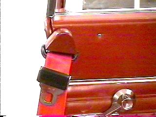
These two photos show the finished assembly. The third point slide bracket that came
with the kit is about 8" long, being designed to use with a roof or pillar mounted
system. As a result, it is unusable when installing it in this location because it
would hit the seat. I got the bracket in these photos off a Dodge Caravan. However,
since the position of this bracket is lower than the shoulder of the person in the
front seat, the belt needs to point upward as well as forward. This particular bracket
when in the Caravan was mounted higher than the front seats and offered little resistance
for the belt to slide through. With this installation, however, the belt is forced
to slide through the bracket at more than a 90 degree angle which adds enough resistance
that the belt doesn't retract well, (which is a shame since it ended up looking quite
nice installed).
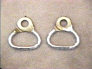
Third point slip brackets from an early to mid 90's Ford Crown Victoria, or the rear
two on the passenger side of a 90's Ford full size van are chromed and, I feel, would
work very well in this installation (however, I haven't installed these in my Falcon
yet, but plan to do so at a later time). The slip brackets shown above are from a
pickup truck I saw in the junk yard. These would probably work well "slip" wise,
but there is no decorative cover with them as there was on the Caravan brackets mentioned
above, and as there is on the Crown Victoria brackets. However, they illustrate how
much better a chromed bracket will perform in this installation than the plastic
coated bracket from the Caravan.
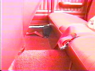
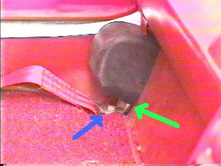
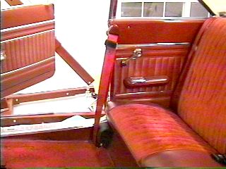
Note in the photos above that the inertia reel is bolted to the rear seat support
(green arrow in right photo), with extra reinforcing washers welded in on the back
side, and the other end of the belt is bolted to the floor (blue arrow right photo),
again with extra reinforcing washers on the back side (the right photo is a close-up
of the left photo). I would have rather mounted the inertia reels somewhere else
where they would be hidden. However, finding a place where it wouldn't get wet (as
it would in the area under the back roll up windows), or a place where the belt would
not get damaged over time due to friction of the belt sliding over trim pieces, seemed
far less desirable than just locating it where it is shown above. This was a fairly
easy installation. In this location, in the outside corner, it is mostly out of sight
and out of the way of passenger's feet.
These particular inertia reels are quite sensitive so the belt must be pulled out
slowly when buckling it up--a slight to moderate irritation. In addition, the harness
is difficult to reach from the front seat if it has retracted fully after the last
time it was used. Sometime in the future, I will modify this installation so that
the belt end bracket will be bolted to the rocker (which is already threaded and
where the original belts were attached) or to the floor right behind the seat. In
addition, I will search junk yards for some sort of plastic belt retainer they used
on the seat backs in the early 70's. This will cause the belt to be permanently attached
to both the rear of the door frame and the front seat backs, thus creating a slight
hassle for those getting in the back seat. I had hoped the installation shown above
would be more convenient for passengers getting in the rear seat, which it is, but
this arrangement is far less than convenient for accessing the belts to buckle them
every time the front seat occupants get in the car--I need to basically leave the
door open, or reopen it to get to the belt if it has fully retracted. I will deal
with a little less convenience in getting kids or other passengers in the back seat,
for far more convenience for the front seat occupants. This is also how new convertible
cars are arranged. When I get these modifications done at some point in the future,
I will modify this page with new photos.
Back Seat Three Point Shoulder/Lap Belts
While I would also have liked to have mounted the inertia reels for the rear seat
somewhere out of sight behind the seat or on the bottom side of the rear hat shelf,
the logistics of routing the belt into the passenger compartment without it receiving
a great deal of wear sliding through cut metal seemed more bother than putting up
with the slight unsightliness of exposed inertia reels. I chose to mount them on
top of the hat shelf on each side as seen below. The other side of the belt is mounted
to the floor under the rear seat bottom in the original seat belt holes (again with
extra large washers).
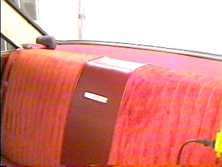
I mounted the inertia reels to the hat shelf metal frame by adding extra large and
thick washers (welded together) to the existing sheet metal framework. The bolt goes
through the masonite wood piece and through the frame. I mounted the inertia reels
at an angle so that the belt would be coming straight out of the reel when the belt
goes over the shoulder of the passenger. Only the two outboard passengers get shoulder
belts, the middle passenger just has a standard seat belt.
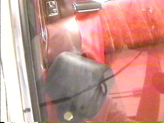
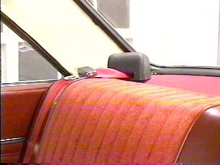
The photo above is looking through the rear window at the hat shelf behind the rear
seat. Although this photo has a lot reflection on the glass, you can clearly see
the mounting and angle of the inertia reel.
Any belt system you add to an older car is pre-made and stitched to a predetermined
length, which may or may not fit your particular application. If the predetermined
length is not desirable for your application, the belts will need to be cut to proper
length, and then re-stitched. Or, if you plan to change the shoulder third point
slip bracket, the belt will need to be unstitched, the end bracket, buckle, and slip
bracket removed from the belt, the new slip bracket, original buckle, and original
end bracket installed on the belt, and the belt re-stitched. Again, as a disclaimer,
the author takes no responsibility for the safeness of the following procedure--you
must decide for yourself if you are comfortable modifying and re-stitching seat &
shoulder belts. If you are uncomfortable, you may be able to find an upholstery shop
who, after you have cut the belts to your needed length, will re-stitch them for
you. Be sure to call first and find a place that will do the re-stitching before
you cut your belts.
Before doing any stitching to a belt you have cut, be sure to "seal" the cut edge
with heat. This can be done with a heat gun, a propane torch, or with matches. Be
careful to not use too much heat as it will melt more of the webbing than is needed
to just keep the cut edge from fraying or unraveling. The propane torch or heat gun
will do the best job, but also can do a lot of damage to the belt if not used patiently.
Work slowly, applying heat just to the edge until the fabric just curls and melts
onto itself--this happens very fast so take your time to avoid ruining the end of
the belt and having to re-cut the belt and try again.
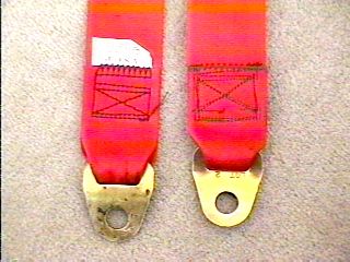
The belt on the left is factory stitched, the one on the right I stitched. The thread
is the same type and size on both belts, the one on the right looks smaller because
I couldn't find any black, and this is gray, which doesn't show up as well as the
black thread in the left photo. The thread is a heavy nylon type, which is available
at some fabric stores, but not all. Take a small sample of the original stitching
with you when buying the thread so you can match it up. If you can't find the thread
at a fabric store, check an upholstery supplier. Note that the stitching on the right
is more substantial than the original. I did this just for extra safety. Note also
that I tried to mimic the stitching pattern of the original. Again, you must decide
if you choose to do this step yourself. Personally, I am comfortable that the stitching
Iýÿdid on the belts in this car will perform as well or better than the original
if it is required to do so (heaven forbid!).
Adding 3-Point Lap/Shoulder Restraints
This is the end of the Adding 3-Point
Lap/Shoulder Restraint Edition
Feel free to save this page to your computer for your personal use and future reference--no
other use is authorized without prior written permission from me. All illustrations
from the 1964 or 1965 Falcon Shop Manuals used pursuant to permission granted by
Ford Motor Company. Disclaimer: This site is not intended to instruct or teach anyone
in proper or safe methods of working on or maintaining any type of vehicle or use
of any tool and the author takes no responsibility for the use of the information
contained herein.