© 1998-


Several options for adding power brakes to our Falcons are available. On the low
end (desirability low end-
When I originally wrote this edition there were only two dual master/power booster combinations that fit our Falcons. One is from a Geo Metro, and the other was offered by a gentleman named Todd Fields. Both these installations will be covered herein. My thanks to Mike Hansen in Illinois for his photos and explanation of the installation of the Geo Metro power booster & master. I installed Todd's setup on my '65 Hardtop. Todd's booster is custom made to fit our Falcons. The master, I understand is GM vintage. The combination seems to fit the '64 & '65 Falcons well.
Since this was originally written, I have run across a third booster that is offered
by Auto Krafters. Their Part number is: PBCDISCKIT. The price is not cheap, $350.
Other Falcon vendors may also carry it so check around. I have not physically handled
this booster, but I understand no modifications to the car are necessary at all.
However, make sure you check and ask specifically about “bolt-
Here are my general conclusions (having installed Todd's and only seen the Geo installation
in photos and read the instructions on the Falcon Discussion Group). The Geo Metro
installation is cheaper if you get parts from a junk yard-
The bottom line seems to be thus: The Geo system is less expensive (with used parts from a junk yard) but requires more work and modification (possibly irreversible) to the shock tower brace. Todd's system is more expensive but easier to install, and requires no modification to the car, and it is insured. Take a look below and decide which is the best system for you and your car's needs.
First let's look at the Geo Metro Installation.
(I will use Mike's narrative he sent with the pictures.)
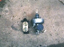
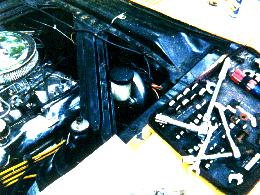
The Geo Booster/Master is a small but effective unit. It consists of three sections; the booster, the dual master with 13/16" bore, and the fluid reservoir. The brake failure warning light is inside the reservoir instead of the proportioning valve, that is why there is a plug coming off the unit. The stock Geo unit looks a bit different than the one pictured here. I prepped this unit by removing decals, sanding, painting, and clear coating the booster, along with cleaning the aluminum dual Master.
The master next to the Geo unit is a 1967 Mustang dual master that I had on my car
before this swap. The Geo booster is working with 1977 Ford Granada front discs and
original five lug rear drums. The booster/master combo has been installed on a Ranchero
with Granada front and rear discs, and has reported no problem of brake fade or premature
lock-
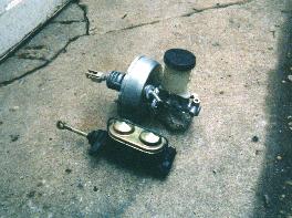
After the holes for the booster have been drilled and enlarged, the reservoir will
barely fit without hitting the shock tower brace. Instead of "massaging" the shock
tower brace to make room, I opted to cut a semi-
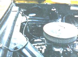
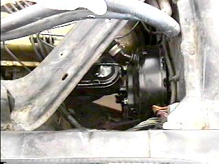
Here's the unit installed without the plumbing. The plumbing was easy, with no impossible bends. I used a Wilwood adjustable proportioning valve in my setup and an happy with the results.
Here's a close-
Now we'll look at Todd's Booster/master installation.
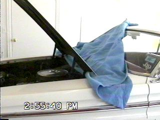
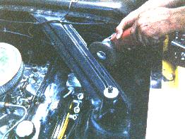
I removed the hood mostly to aid the videoing of the installation. However, I found that the installation went so much easier with it removed that I would strongly recommend removing it. Put an old blanket or something similar between the back of the hood and the cowl so that if the hood slips down after the bolts are removed, the paint won't be damaged. Anytime you are working with brake fluid, protect the painted areas as much as possible since brake fluid acts as a paint remover.
This is the old dual master with the associated plumbing and adjustable proportioning valve. The black hoses are air conditioning lines.
The left photo is after removal of the old master and re-
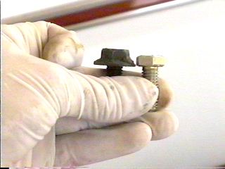
This photo shows one of the upper bolts for the brake/clutch pedal support bracket mentioned above. These bolts can be replaced with ones having smaller heads which will allow the booster to fit a bit closer to the firewall and aid clearance with the shock tower brace. I replaced the original bolts with Grade 8 bolts from the hardware store. You can see the difference in the height of the head of the bolts. Believe it or not, this makes a difference.
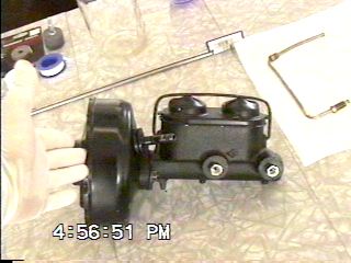
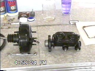
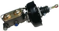
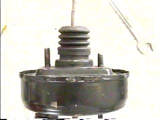
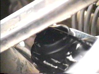
This is the booster & master combination. I needed to separate the master from the
booster because together I couldn't get the unit past the shock tower brace from
the top, or from the bottom because the engine was in the way. Notice in the right
photo the push rod coming out the front of the booster that goes into the master.
It is adjustable in length. If you find that brake application starts too soon after
the pedal is pushed, you can adjust the rod shorter which will allow pedal movement
before the master starts engaging the brakes. Todd reported that in some instances
the brakes actually drag with the rod at the shipped length. I would recommend adjusting
the rod shorter before installation to lessen the possibility of needing to remove
the master to adjust the rod after installation. (In my case, the brakes were dragging
quite a bit with the rod at the shipped length. I finally ended up with this rod
adjusted almost all the way in-
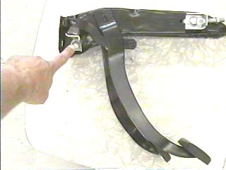
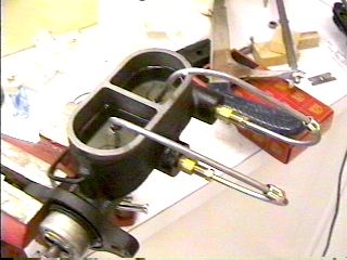
The left photo shows the brake/clutch pedal support that I have restored from my
'64 Sprint. The '65 I installed this system in also has a clutch pedal (for now-
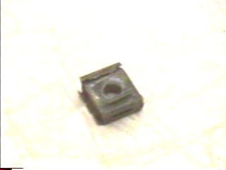
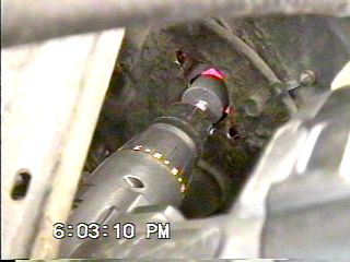
This is one of the blind nuts removed from the lower two holes of the brake/clutch pedal support bracket. I removed mine by sticking an old screwdriver in the hole and hitting the screwdriver with a hammer. One blind nut broke completely free, the other broke free only on one side and needed to be grabbed with some pliers from under the dash and pulled the rest of the way off. This part was easy, two minutes max.
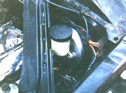
The booster installed (note again the adjustable push rod from the booster to the master). Before tightening the nuts down on the passenger compartment side of the firewall, make sure to install the pushrod onto the brake pedal arm with the nylon bushing provided and the original clip you pulled off to remove the old master, then tighten the nuts. If you wait till the nuts are tight, there won't be enough play in the push rod to get it on the brake pedal arm. Note also that you will need to add a good size washer on the stud before the nut since there is a square hole where the blind nut was removed from and the nut alone will eventually push through the hole leaving you with no brakes. You should also install a lock washer between the washer and nut. The two nuts on the threaded studs of the booster are the only things holding the booster/master in place while you stomp on the brakes in a panic stop. Don't scrimp here! Do it right and make positive the booster is secure and tight!
Before installing the master in the car it needs to be bench bled. If you've never done this before, you do this by putting the master in a vise. I got some short 3/16" tubing and bent it to fit in the reservoirs so that the ends in the reservoirs will be below the fluid level. Add clean brake fluid to above the ends of the tubing. Then insert a wooden dowel into the end of the master (where the pushrod from the booster will go) and SLOWLY and carefully push the dowel in and out repeatedly until no more bubbles are seen while pushing the dowel in. Use plenty of shop rags or paper towels around the master. If you accidentally push in too fast on the dowel, brake fluid will spurt out of the reservoir and make a mess. After bleeding the master, remove the tubing, fill the reservoirs, and replace the cover. (Note that there will be some slight dripping from the ports when the master is full and no lines are attached. You may want to get some plugs for the holes to prevent this while you move the master to the car, install it, and modify and install the lines. If you do not get plugs, use rags to prevent a mess.)
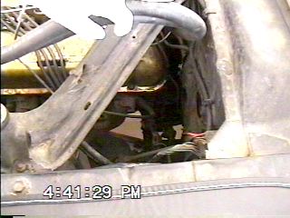
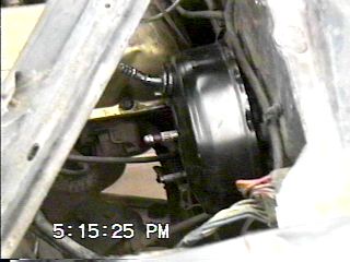
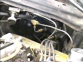
The master is mated back with the booster. The vacuum line is also attached. The right photo is from the windshield area looking toward the front of the engine compartment at the fit of the master with the shock tower brace. You can't see the actual clearance but it is about 1/8". I must mention the scuffed state of the paint on this unit is my fault. When I got the unit it was in perfect appearance. I have had it for some months and have moved it here and there and the paint has suffered.
This is how I hooked up the plumbing. I was in a rush and my only goal at this point
was to get it installed and working so I could get this web site out as promised
(I will be putting a new engine and C4 in the car in a few weeks and will re-
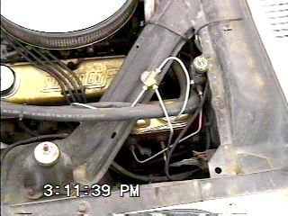
On a '64 Falcon the brake lights are activated through a hydraulic pressure switch
in the brake system which closes the contacts when the brakes are applied (this switch
was originally installed on the master cylinder). To accommodate Todd's system in
my '64 Sprint, I needed to come up with suitable plumbing to accommodate the hydraulic
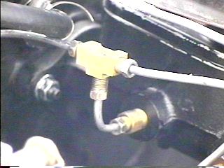
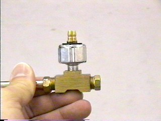
pressure brake light switch. In the photo above is a fitting that has 5/16" flared
holes in each end, and a 1/8' pipe thread hole in the top which is what is required
for the stock pressure brake light switch (which is screwed into the hole in the
top of the fitting). The switch is installed in-
On a '65 Falcon the brake light switch is on the brake pedal itself and is a physical pressure switch, sensing pressure between the brake pedal and the pushrod to the master or booster. When installing Todd's system in my '65 hardtop, the booster put enough backward pressure on the pedal that the brake lights were on all the time. Todd's boosters have a threaded adjustment on the pushrod from the brake pedal to the booster to adjust for some free play so this brake light switch functions properly.
This is the end of the
Adding Power Brakes Edition

Feel free to save this page to your computer for your personal use and future reference-
If you have comments or suggestions, email me at joe@joesfalcon.com
Adding
Power
Brakes
Overview