
© 1998-


The air vent assembly for the driver sits under the left side of the dash and attaches
to the left side of the fresh air cowl in similar fashion as the heater is attached
to the right side of the cowl. The restoring of this assembly to good-
Discussion & Procedure
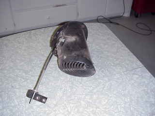
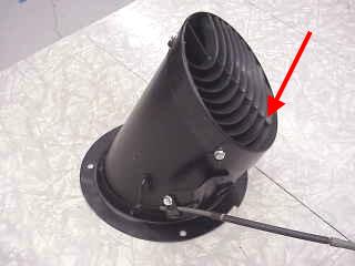
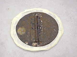
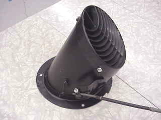
This is the unit as it looked when removed from the car. The paint on the main body was not in too bad a shape, but it was scratched up a bit with some rust forming on the scratched areas. The interior parts were quite a bit more rusty as can be seen in the right photo.
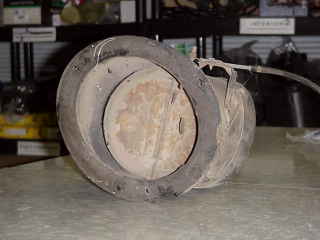
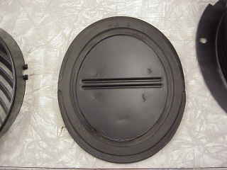
This is the mounting flange that mounts to and seals against the cowl. As with the heater, it is sealed by a closed cell foam donut. As was the case with all the foam seals in my heater, this foam seal was totally deteriorated and not sealing at all. It would reduce to dust when touched.
These photos show the rubber-
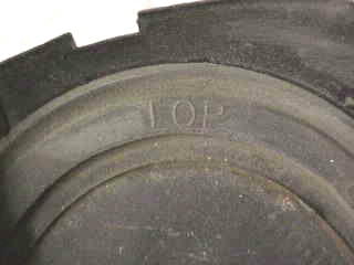
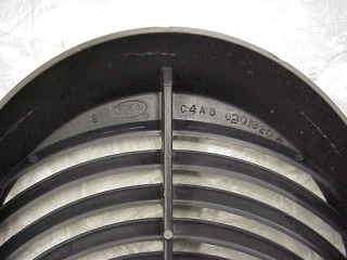
This photo is the other side of the butterfly valve (before disassembly) looking from the side that is exposed to the interior of the car when the valve is closed (this was just after the plastic face grill was removed). Notice how much better shape this side of the valve is in. The valve has the word "TOP" molded into the rubber. This can be confusing. It would tend to make one think that this side of the valve is installed so that it points toward the top of the unit when the unit is installed in the car. However, it is just the opposite. The photos below show where the "TOP" indicator goes in relation to the main body.
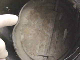
The red arrow in both photos is pointing to the same place on the main body, and this is where the "TOP" indicator on the butterfly valve goes. The left photo was taken during disassembly and is looking down into the unit after the plastic face grill was removed. The right photo is after everything was restored and the unit reassembled.
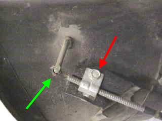
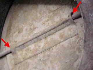
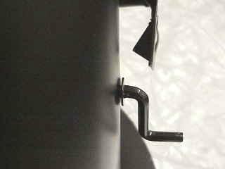
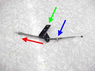
To begin disassembly, remove the control cable by removing the screw and cable stop (red arrow, left photo) and then slide the coil of control cable wire off the control rod (green arrow, left photo). Next, on the other side of the unit, remove the hitch pin and washer from the opposite side of the control rod (green arrow, right photo). Now the control rod needs to be removed. To do this (after the above steps have been completed) tap on the tip of the control rod that is shown by the green arrow in the right photo. The corrosion level of the butterfly and control rod valve will determine the effort required to remove the rod (again, if you previously sprayed some rust loosener into the the channel it will make this much easier). Mine began moving after only a few firm taps with a small hammer. The sides of the rubber on the butterfly valve (by where the rod goes through) is very thick and firm so the light hammering on the control rod will not damage the delicate rubber edge on the rest of the butterfly valve. Although I don't have any photos of this, once the rod is clear of the edge of the main body, you can use a pin punch to continue driving the rod out of the butterfly valve as far as possible. If you do not have a suitable pin punch, once the one side of the rod is clear of the main body the valve will move freely and you can angle it upward enough to continue tapping the rod with a small hammer to dislodge it from the valve.
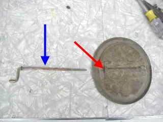
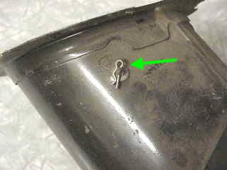
This photo shows the rod removed from both the butterfly valve and main body. Although it will be seen more clearly later on, where the blue arrow points is a flat spot on the rod that, when the rod is fully seated in the butterfly valve, keeps the rod from slipping inside the channel in the valve. Once this flat spot is free of the valve, it is fairly easy to rotate the rod back and forth in the channel while holding the butterfly valve still, while at the same time pulling on the rod to get it out of the main body.
Rebuilding
The Driver’s
Air Vent
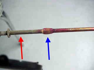
The left photo shows a better view of the flat spot on the control rod. Also, starting with the blue arrow (left photo) and going to the right, the original finish on the rod can be seen. It was fairly clean and shiny with a reddish cast to it. On both ends of the rod, however, there was some corrosion as seen by the red arrow in the left photo. The blue arrow in the right photo shows the slotted hole in the main body where the control rod slides into.
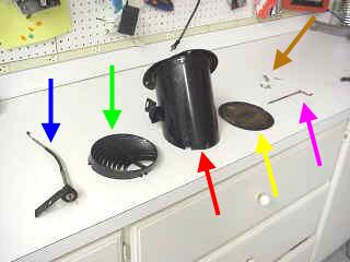
The left photo shows the unit completely disassembled. The blue arrow points to the
control cable assembly, the green arrow points to the plastic face grill, the red
arrow points to the main body, the yellow arrow points to the rubber-
I decided to media blast the butterfly valve to bare metal. I was worried that the rubber might be damaged so I carefully masked it off as seen in the left photo. The right photo shows the butterfly valve after media blasting, priming, and painting. A circle of less rust can be seen in the left photo which must have been some sort of part sticker that later came off.
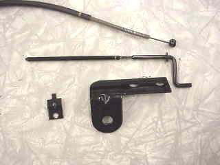
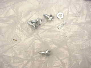
As seen in the edition on powder coating, these parts for the vent unit were powder coated (just the coiled tip of the control cable was powder coated). This will give an attractive and long lasting protective finish to these parts. The larger piece in the lower center of the photo is the bracket for the control cable that mounts it to the bottom of the dash (it uses the same screws as the parking brake assembly and mounts just to the right of it). If you do not have powder coating ability stripping, priming, and painting these parts will do just fine.
After everything is cleaned and refinished it is time to reassemble the unit. The
control rod will need to be tapped again with a small hammer to get it through the
tight-
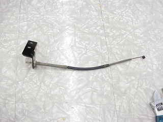
As mentioned above I removed the bracket for the control cable to hot coat it. To reinstall the bracket, slip it on the cable from the coiled side of the cable (be sure to install it with the bend in the bracket pointing toward the end of the cable that the pull knob goes on as seen by the green arrow) along with the nut (blue arrow), and slide it on the cable in the direction of the red arrow till it is fully seated, then tighten the nut on the back. The right photo shows the bracket installed properly. If the bracket is installed backwards it will interfere with the parking brake assembly.
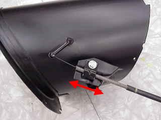
Now install the control cable on the main body in the opposite sequence in which you removed it. Before fully tightening the screw, check to make sure the adjustment is close (final adjustment can be made in the car if necessary). To do this, temporarily install the vent knob on the control cable end and push it fully in. Then slide the cable in or out (red arrows) till the butterfly valve is tightly closed, then tighten the screw. If the cable is too far out you won't be able to fully close the vent, if it is too far in the vent knob will stick out when the vent is closed, and you will not be able to open the valve fully.
The plastic face grill was extremely dirty. I once drove the car over 110 miles of dirt road back in the '70s and I'm sure most of the dirt on this grill was from that day. I tried brushing it with soap and water, but I was unable to get into all the tight areas. The only way it finally came completely clean was to put it in the dishwasher (be sure to put it on the top rack and don't leave it in long or it may start to melt and distort). The right photo shows it installed. It can only go on one way.
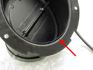
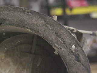
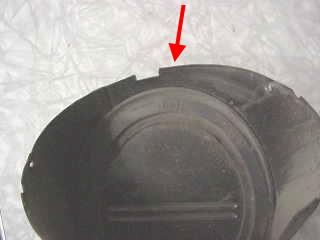
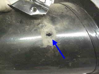
The red arrow in this photo shows a gap between the mounting flange and the main body "can". This had been sealed with some sort of paintable rubberized sealant which was mostly removed during media blasting. Although not shown here, I sealed this up with black silicon sealer, taking care to not get much on the mounting flange face (since the adhesive for the foam donut seal will not stick to silicon sealer). If this is not sealed, a small amount of outside air will come into the car even when the vent is "off", which, on a cold day, can be annoying.
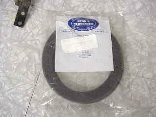
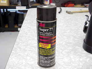
The left photo shows a new foam donut seal that goes between the mounting flange and the cowl. As with the foam seals in the heater, I will use 3M Supper 77 spray adhesive to glue the seal to the unit just prior to installation in the car. Be sure to spray the adhesive onto the foam seal and then carefully position the seal onto the mounting flange rather than spraying the adhesive directly on the mounting flange (the overspray will ruin the looks of the newly painted surfaces and will attract a lot of dirt).
Overview
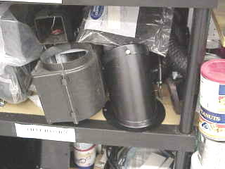
For me, the best part of finishing with any part is putting it on the shelf with other new or refurbished parts to await installation.
This is the end of the
Rebuilding the Driver’s Air Vent Edition

Feel free to save this page to your computer for your personal use and future reference-
If you have comments or suggestions, email me at joe@joesfalcon.com