
© 1998-


Front
Suspension
Part 5
Assembly & Installation (continued)
Installing the Stabilizer (Sway) Bar
Installation of the stabilizer bar is very simple and takes less than an hour. It is easier to install with two people but one can do the job without a great deal of difficulty.
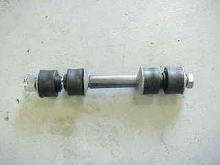
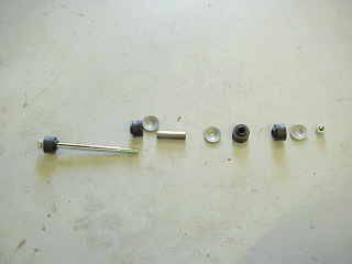
First, install the links into the lower control arms per instructions with the link/bushing kit. The link is nothing more than a long bolt with some rubber or polygraphite bushings, some concave washers, and a spacer as seen in the above photos.
Install the link into the lower arm as seen above, leaving the top bushing, washer and nut off for the time being.
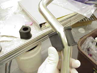
Before installing the stabilizer bar, you need to install the rubber insulator bushings
(for the mounts to the frame) onto the bar itself. If you are installing rubber bushings
they will need to be installed by sliding them onto the bar from each and and working
them to where they ride. Using some swimming pool O-
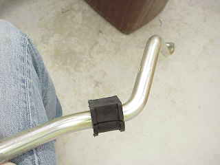
These two photos show where the bushing are to be installed on the stabilizer bar.
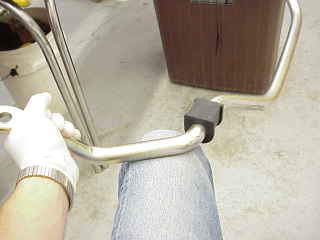
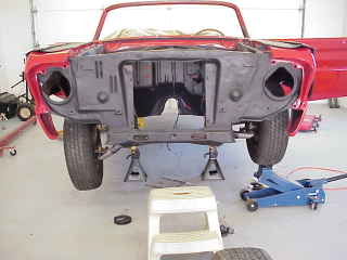
Some frame bushing kits allow the frame mounting bracket to be pushed onto the bushing and it will stay well enough to hold in position during installation, while others will not. If the brackets will stay on the bushings firmly, go ahead and install them on the bushings. If they will not stay firmly on the bushings, simply set then on the floor where they are easily accessible. Set the bar on the floor under the car and have the frame brackets and bolts ready at hand by the bar. Next, from the bottom, lift the bar up and to the side to get the end of one side of the bar above the strut rod. It doesn't matter which side you start with, but for purposes of illustration let's start buy lifting the passenger side of the arm up and over the passenger side strut rod and back into the passenger side wheel well. This will allow the driver's side end of the stabilizer bar to get above the driver's side strut rod.
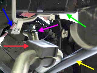
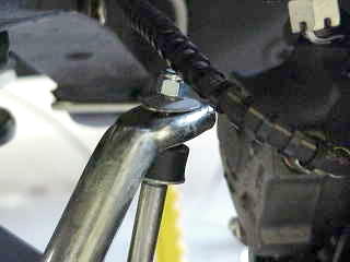
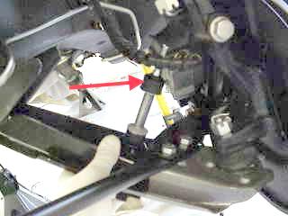
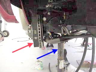
After the bar is above both strut rods, set the holes in the ends of the bar on the links on each side and then temporarily install the top concave washer and nut on the link to keep the end of the bar on the link as seen in the above photos. The left photo above is taken from just under the radiator support and is looking toward the driver's side suspension. The pink arrow points to the bar set onto the link with the washer and nut temporarily installed. The yellow arrow points to the strut rod and shows the stabilizer bar resting on the strut rod prior to its being raised up to the frame mount. The red arrow points to the left (driver's side) stabilizer bar bushing. The green arrow points to the frame mount for the stabilizer bar. The blue arrow points to a retaining clip on the fuel line that attaches to the rear mounting bolt of the stabilizer bar.
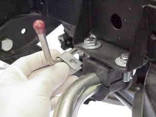
This photo shows the bar raised up to the frame mount (although the bracket is not yet installed around the bushing). It also shows the fuel line clip more clearly. Now add the bushing bracket around the bushing and install and torque the bolts and nuts. After the bushing brackets are mounted to the frame, remove the concave washers and nuts from the links, install the upper bushing on the link and reinstall the washer and nut and torque them to the proper specification.
Rough Check the Alignment
It will be helpful and beneficial if you can at least "eyeball" the front wheel
alignment and add/remove shims to get the wheels as close to perpendicular to the
road as you can, and adjust the sleeves on the tie rod ends to get the toe in/out
of the wheels as close to straight ahead as possible before you try to drive the
car. It is easiest to perform this check and make any adjustments before the springs
are installed and while the front end is still on jack stands. This is especially
true if the upper arms have been lowered. If you have already installed the springs,
and/or you wish to wait till the job is complete prior to making any adjustments,
then you must wait until the engine/transmission is installed and the car has settled
to its at rest height above the road. A word of caution here: simply lowering the
car back onto the tires will not give you a good enough idea where the wheels are
going to ride from an alignment standpoint. The car must be driven or pushed at least
10 or 15 feet before the tires and wheels will settle to their new at rest position,
especially if the upper arms were lowered. If you subsequently raise the car on a
jack it will need to be moved again the 10 to 15 feet before you look at the alignment
and make adjustments. I can't stress this enough. When I first modified my '65 by
lowering the upper control arms, I simply kept the same shims and replaced them exactly
as they had been. I looked at the toe on the tires and it looked quite good; however,
I hadn't moved the car at all and it hadn't settled to its new ride height. When
I went to drive the car, it settled much lower than it was right after it was simply
lowered onto the garage floor. The alignment was so far off that I found it very
difficult to keep the car under control -
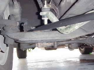
As a guide, the left photo above shows the "at rest" angle of the lower control arms on my '65 after the upper arms were lowered and the front end was aligned (this photo was taken with all tires on the ground after the car was driven and represents the true "at rest" position of the arm). This gives a ballpark idea of where the lower arm should ride after the upper arms have been lowered. As seen above, it will be helpful in visualizing alignment to temporarily install the tire/wheel assembly; however, it can be done without the tires installed. Now, as seen in the right photo, while the car is resting on jack stands (and before the spring is installed) place a floor jack under the tire (or the brake drum/disc if you are not doing this with the tires installed) and slowly jack it up. Make sure the frame of the car stays firmly on the jack stands. Continue until the lower arm looks similar in angle to the left photo.
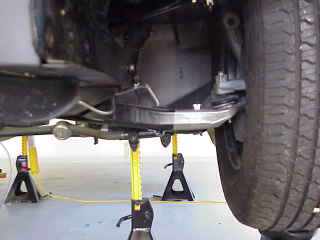
The photo above shows the left wheel jacked up to its approximate new ride height. If you have an additional pair of jack stands, install one under each lower arm so that both wheels are at the same height.
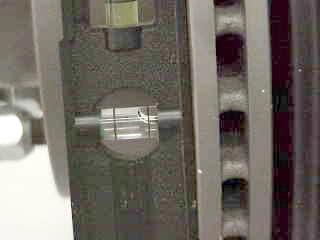
If you decide to not install the tires for this rough check of the alignment, a magnetic
torpedo level (red arrow in left photo) can help better visualize the camber adjustment.
The blue arrow in the left photo points to a jackstand installed under the lower
control arm. I jacked up both sides to the same height and installed jack stands
under both lower arms for the rough alignment check and adjustment. Add or remove
shims between the upper control arm and frame until the wheel is as close to perpendicular
as possible (if you threw away or lost your old shims, or you do not have enough
shims to make a good adjustment, you should be able to get some from a front end
alignment shop -
While the wheels are temporarily jacked up for the camber adjustment check, be sure to check and adjust the wheel toe in/out. If you have two people who can help you, the steering toe check will be easier than doing it alone. First, make sure the steering wheel is at the center of its left/right travel. Have one person hold a long straight edge (such as a four foot framing level or a yard stick) along the bottom edge of one of the brake discs or through the hub area of one of the brake drums and extend the straight edge out the front of the car. Have the second person do the same thing on the other brake. Now you can stand in front of the car, or get on a ladder or step stool at the front of the car and look down at the two straight edges and see if they are both pointing straight ahead (not pointing to one side or the other) and that they are parallel to each other. If they are not, make adjustments to the sleeves on the tie rod ends to get the wheels straight ahead and parallel to each other. If you do not have someone who can assist you, you can try to lightly clamp the straight edges to the disc or drum, or you will need to simply try and visualize the alignment. Again, if must do a visual check with no long straight edges it will be easier to visualize alignment with the wheels/tires installed. For this check I temporarily installed the steering center link and tie rod ends and then removed them until after the engine/transmission was installed (I find it much easier to mate the transmission to the engine before installing them in the car; however, installing the engine/transmission assembly as a unit is nearly impossible if the steering center link is installed, thus I removed it until after the engine and transmission are installed).
Later, after the car is complete (front springs are installed, engine and transmission installed, etc.), lower the car and move it 10 to 15 feet and check how the alignment looks. If it does not look aligned to you, add/remove shims or adjust the sleeve(s) on the tie rods again and keep doing this till you get the wheels as close to proper alignment as you can. When it looks satisfactory, drive the car very slowly in an area where you can stop quickly if needed (such as a sleepy neighborhood) and see how it drives. If you feel it is safe enough to drive on the open road (i.e. the car steers and drives normally with no serious pulling to one side or the other) then drive it slowly and carefully to your alignment shop and have it adjusted to specs. Again, many garages that perform front end alignments will not align a car if the front and has been lowered or otherwise modified from stock. If you have lowered the front arms, before taking the car to an alignment place be sure and check with them to make sure they will do the alignment and what the cost will be.
Installing the Springs
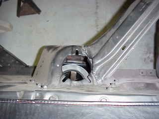
As mentioned previously, before installing the spring make sure you replace the frame bumper since the nut that holds it in place is not accessible after the spring is installed.
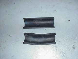
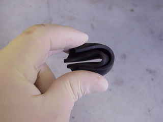
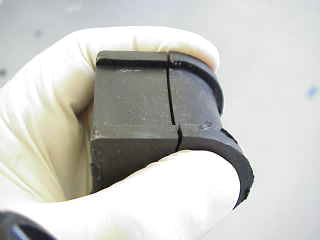
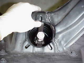
Before the spring is installed the rubber insulators that go between the spring and the perch need to be put in place on the perch. The top insulator in the left photo above shows that when shipped the rubber insulator strips for the perch are straight. To put a curve in the insulator so it fits the curve of the spring, pinch the ends together, as seen in the right photo, and let it sit loosely in a vice or with a weight on it for about an hour or so. When it is released it will have a slight curve introduced to it that fits the spring better, as can be seen by looking at the lower insulator in the left photo above. Also, it is difficult to keep the insulators in place on the perch while the spring is being uncompressed so it helps to cement the insulators in place on the perch with contact cement or other suitable adhesive before installing the spring.
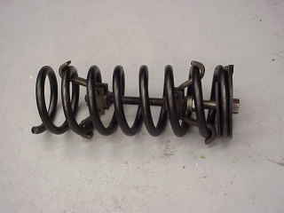
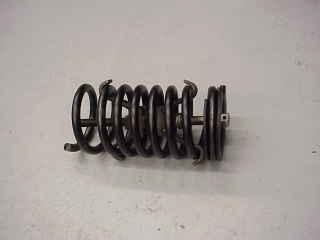
Before the spring can be installed it must be compressed with an internal spring
compressor as can be seen above. Be very careful here as a compressed spring carries
a lot of energy trying unleash itself -
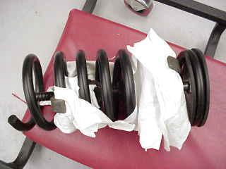
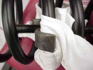
If you painted, powder coated, or otherwise refinished your springs, be sure to protect
the finish during installation. I had previously installed the springs in the car
to allow transporting the car to the painter, and then later removed the springs
to refinish them (hence, some of the photos seen below will show the springs in the
compressor without any protection for the finish). Since I went to the effort of
stripping off the poor finish that came on these new springs and then powder coated
them, I used some rags from an old T-
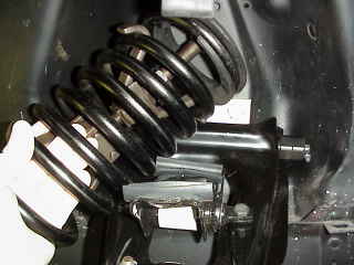
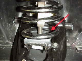
The compressed spring is installed at an angle as seen in the left photo. The top
end (with the rubber insulator installed) is then directed up into the shock tower
and the bottom coil is set on the rubber strip on the spring perch as seen in the
right photo. Note that there is a stop for the end of the bottom coil to sit against
(red arrow in right photo). Note also that only one side of the spring is resting
on the perch at his point. The other side will come in contact with the perch as
the spring is uncompressed. Note also in these photos that the paint on the outside
edge of the spring has been worn off from handling and shipping. The rest of the
paint, at least on these springs, seems to be nothing more that barely enough protection
to keep the spring from rusting during shipping, but certainly would not be adequate
long-
Before uncompressing the spring, make sure it is centered in the shock tower as seen in the photos above. Also, though not shown in these photos, you may want to install the bolts for the shock absorber brackets if you can before the spring is completely uncompressed. While some bolts will slide into place with the spring installed, some heads on some bolts are thick enough that it will be hard to install them later. On this car I placed all six bolts in place as I uncompressed the springs but five of the six were still loose after the springs were fully uncompressed so I removed them for safe keeping till later and left the one in place.
Uncompressing the spring is a two handed operation -
This is the end of the Front Suspension Edition

Feel free to save this page to your computer for your personal use and future reference-
If you have comments or suggestions, email me at joe@joesfalcon.com