
© 1998-


In my case the wedge was added between the ball joint and the upper arm.
Since the bolts were now at an angle to the top surface of the arm, the nuts that
came with the lowering kit had been pre-
Replacing the Pivot Arm
The pivot arm is also fairly easily replaced, but care must be taken when reinstalling the new one. While I had new reproduction upper control arms, when I went to install them I found that one of them wouldn't fit the holes in either shock tower (it wouldn't fit the original set of holes on either side, or the new set I had drilled on either side). Since I had already modified the arm by replacing the ball joint I knew that a warrantee replacement of the arm was out of the question, so I needed to replace the pivot with one that would fit.
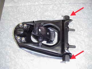
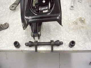
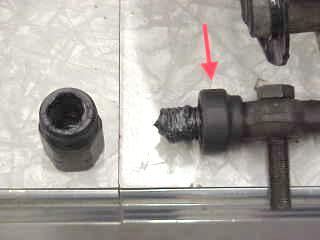
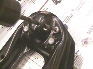
To replace the pivot, simply loosen and unscrew the end caps from each side (red arrows left photo) and remove the pivot bar.
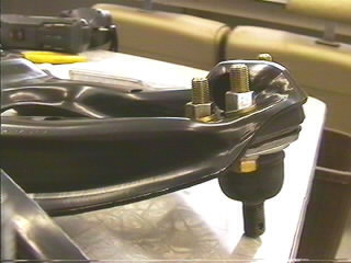
While new complete upper arms come with the mounting bolts already installed in the
pivot bar, new pivot kits don't. At some point these need to be installed into the
pivot with a fair amount of force since the shaft near the bolt head is deeply splined.
The splined portion of the shaft, once firmly seated into the pivot bar, is designed
to keep the bolt from turning while the nut on the engine compartment side of the
shock tower is tightened. (In addition, some recommend putting a small tack weld
between the bolt head and the pivot bar just for good measure-
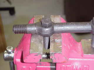
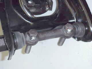
To install the bolts in the pivot I opened the jaws of the vice just larger than the size of the bolt and set the pivot on top of the vice. I then inserted the bolt in the hole as far as it would go and drove it into the pivot with a hammer which took several hard swings to drive it fully in place. I tack welded the bolts to the pivot as seen in the right photo and later touched them up with paint for corrosion protection.
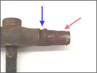
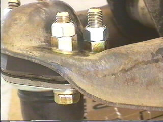
As an aside, the left photo above is of the pivot removed from my '64 Sprint while the right photo is of a new one and shows what it should look like. Note in the left photo that the coarse threads that hold the pivot firmly in place in the arm are totally worn away (red arrow) and that the end cap had worn a groove in the shaft (blue arrow). The one on the left had over 300,000 miles on it and it was so worn that the upper arm was a bit loose and could be wiggled back and forth in the car. Such wear would make an accurate front end alignment impossible, and, although these symptoms were not present in this Sprint, could induce handling and shimmy problems. In addition, it is difficult to tell at what point the worn grove made by the end cap would have weakened the pivot enough to allow it to break under stress which would likely result in loss of control of the car.
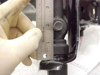
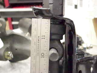
To install the pivot, first set the pivot in place in the large holes in the sides of the arm. Then screw the end caps onto the pivot, and then into the arm itself. The pivot must be centered in the arm so take careful measurements. As mentioned above, it is much easier to center the pivot without the bolts installed since you can simply turn the pivot one way or the other which will move it left or right until it is centered. If you chose to install the bolts first you must center the pivot by alternately loosening and tightening the end caps. However, the end caps thread onto the the pivot with a very course thread, then they also screw into the arm with a fine thread so it is a challenge to get them just right this way. The shop manual shows the centering done without the bolts installed.
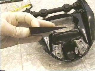
Once the pivot is installed and centered in the control arm, the end caps need to be torqued properly. The 1964 shop manual simply states to torque the end caps to specification. On the other hand, the 1965 shop manual shows a different procedure. It directs taking a piece of 3/4" pipe or stock steel, cut to 7 7/ 16 ", and placing the piece between the flanges of the control arm and then torquing the end caps to the specified torque. Since the arms are identical '64 to '65, one must assume that Ford engineers were either concerned that the arm sides could become distorted with the required torque, or they were actually finding that this was happening in the field. Either way, the specially cut piece of steel was intended to keep the arm sides in place during tightening. Since I had already torqued mine and installed them in the car before I came across the other procedure in the '65 manual, mine are simply torqued as specified in the '64 manual. If I had it to do again, however, I would go to the extra effort specified in the '65 manual.
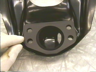
Most new pivot arms (and complete new/reproduction upper control arms) have provision
for a grease zerk in the end cap of the pivot arm for lubrication. It should be mentioned
here that there are two types of seals being installed on these pivot arm bushing
caps. One has an "O" ring seal in the end cap and the other has a flexible (sort
of inflatable) boot on the outside of the cap which is shown by the red arrow in
the left photo above. In my opinion, the latter is recommended if you have a choice.
The reason is that the "O" ring seals so well that air can not escape when you are
attempting to inject grease into the end cap. As a result, grease will not flow into
the pivot arm well and down the road when the pivot arms start to squeak you may
not be able to stop it by trying to grease the end cap. With the boot-
This is the end of the Front Suspension Edition
Part 2

Feel free to save this page to your computer for your personal use and future reference-
If you have comments or suggestions, email me at joe@joesfalcon.com
Ford mounted the ball joints to the control arms with rivets. Therefore, replacing the original stock ball joint requires drilling out the rivets that hold the ball joint to the arm. To do this, carefully position a center punch in the center of the top of the rivet head and use a hammer to make a good deep dimple. Using a 1/4" drill bit, drill through the head of the rivet till it is almost to the control arm. Then use a cold chisel and hammer to knock the head of the rivet off (right photo above). Then tap the shaft of the rivet out the bottom of the ball joint with a pin punch. Do this for the other three rivets in the arm. The ball joint should then be easy to remove. If you are not installing a lowering kit, simply install the new ball joint with the bolts & nuts provided per the instructions that came with the ball joint. (If you are going to paint or powder coat the arm then wait to install the new ball joint till after the arm is refinished.)
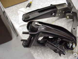
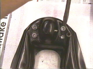
The photo immediately right shows both upper control arms, one right side up and
the other upside down (both arms are 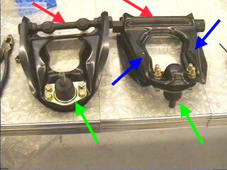 identical and interchangeable from left to
right side). The upper control arm consists of the arm itself, a ball joint for
mounting the arm to the spindle (green arrows), a pivot arm and bushing kit for mounting
the arm to the shock tower (red arrows), and a spring perch to hold the front spring
(blue arrows show the mounting location for the spring perch although it is not installed
in this photo). If the upper arm itself is in good shape (not bent, cracked, or rusted),
replacing the ball joint, the pivot arm & bushings, and the spring perch will restore
the arm to good-
identical and interchangeable from left to
right side). The upper control arm consists of the arm itself, a ball joint for
mounting the arm to the spindle (green arrows), a pivot arm and bushing kit for mounting
the arm to the shock tower (red arrows), and a spring perch to hold the front spring
(blue arrows show the mounting location for the spring perch although it is not installed
in this photo). If the upper arm itself is in good shape (not bent, cracked, or rusted),
replacing the ball joint, the pivot arm & bushings, and the spring perch will restore
the arm to good-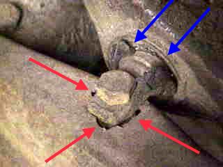 replaced. New or reproduction replacement arms come
complete with a new pivot arm/bushing and a new ball joint and, after installing
the spring perch, are ready to install in the car. Although new replacement arms
do not come with a new spring perch, these are also available and should be replaced
at the same time since the rubber bushing in the perch is often deteriorated. I chose
to replace my upper control arms with new reproduction ones. These arms are available
new from Ford, or reproduction arms are available from the usual Falcon and Mustang
vendors. Of course, the Ford arms cost quite a bit more than the reproduction arms.
Some feel the Ford arms are better quality, others feel there is no distinguishable
difference. Although I bought new reproduction upper control arms for my Sprint,
since I was adding a Negative Wedge Camber kit I needed to go through the process
of replacing both the ball joints. Also one of the pivot arms was defective so I
needed to replace it. As a result, the procedures for completely refurbishing your
old upper arms will be covered. Even with new arms the paint finish is often damaged
to one degree or another just due to bangs and bumps during shipping and installation.
Where the paint has been damaged and bare metal is showing, rust will result in these
areas. If you are planning to build a "show queen" and want it to look brand new
forever more, or if you want to have as complete protection from rust and corrosion
as you can get, you may consider removing everything from the new arms, striping
them, and repainting or powder coating them. At a minimum, you may want to touch-
replaced. New or reproduction replacement arms come
complete with a new pivot arm/bushing and a new ball joint and, after installing
the spring perch, are ready to install in the car. Although new replacement arms
do not come with a new spring perch, these are also available and should be replaced
at the same time since the rubber bushing in the perch is often deteriorated. I chose
to replace my upper control arms with new reproduction ones. These arms are available
new from Ford, or reproduction arms are available from the usual Falcon and Mustang
vendors. Of course, the Ford arms cost quite a bit more than the reproduction arms.
Some feel the Ford arms are better quality, others feel there is no distinguishable
difference. Although I bought new reproduction upper control arms for my Sprint,
since I was adding a Negative Wedge Camber kit I needed to go through the process
of replacing both the ball joints. Also one of the pivot arms was defective so I
needed to replace it. As a result, the procedures for completely refurbishing your
old upper arms will be covered. Even with new arms the paint finish is often damaged
to one degree or another just due to bangs and bumps during shipping and installation.
Where the paint has been damaged and bare metal is showing, rust will result in these
areas. If you are planning to build a "show queen" and want it to look brand new
forever more, or if you want to have as complete protection from rust and corrosion
as you can get, you may consider removing everything from the new arms, striping
them, and repainting or powder coating them. At a minimum, you may want to touch-
When building cars it is impossible (at least with present day mass production technology)
to make it perfectly and keep all the parts in perfect alignment. As a result, the
front wheels are placed into precise alignment after the car is completely built.
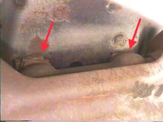
In the cars of this era, the upper control arm was loosened and shims (red arrows
left photo) were placed between the arm and the frame to get the wheel exactly where
it needs to be (the photo on the left shows the upper control arm still installed
in the car -
Replacing the Ball Joints
Refurbishing Individual Components
Upper Control Arm
Front
Suspension
Part 2